Considerations for Planning and Selecting Pumping Plants for Sprinkler Irrigation
DOWNLOADNovember 6, 2023 - Younsuk Dong and Lyndon Kelley, Michigan State University Extension
 Print
Print Email
EmailIntroduction
The pumping plant generally accounts for a substantial portion of the initial cost and a major portion of the annual operating cost associated with a sprinkler irrigation system. Over 90% of the energy used by an irrigation system is used by the pump. The selection of the pumping plant, then, has a significant influence on the economics of irrigating. Careful planning and selection of this essential component helps to ensure both the adequacy, efficiency, and viability of the entire irrigation system. An irrigation pumping plant consists of a power unit, a pump, and all required accessories such as piping, valves, gauges, safety equipment, and mounting platforms. This bulletin deals with the two primary components: the power unit and the pump.
Requirements of the Pumping Plant
Flow Requirement
The first step in planning a pumping plant is to determine the desired flow, the required pressure, and the type of water source. An acceptable method for determining irrigation flow requirements involves considering the peak daily water use of the crop to be irrigated. Daily peak use estimates for a variety of agricultural crops under Michigan conditions are presented in Table 1. This table is based on average reference evapotranspiration (rET) from the last 10 years. In addition to the daily peak use, some water evaporates before it enters the soil. For example, when corn is in the tassel emergence (VT) stage, evaporation occurs at a rate of 0.07 inch from the canopy and 0.03 inch from the soil surface. Thus, the peak daily water use and these evaporation rates should be considered. Table 1, along with equation A, can be used to estimate flow requirements. The ability to irrigate continuously during the peak crop water use period is assumed in this approach. If this ability does not exist with a particular system, the required flow should be increased by the appropriate percentage. In addition, the number of acres should include all future acres that may be added later to the site.
Equation A: Field size (acres) x Peak daily use (inches) x 18.86 = Required flow (gallons per minute)
For example, assume a farmer wishes to irrigate a corn field. The field size is 80 acres, and the peak daily use (from Table 1) is 0.28 inches. Using equation A (80 x 0.28 x 18.86 = 422), the needed flow is 422 gallons per minute (gpm). This example will be extended through this discussion.
Depending on the distribution equipment, there may be a minimum flow to operate the system. For example, big gun traveler systems typically are laid out as a 30-feet by 13,120-feet rectangle requiring 450 gpm or greater and 150 foot throw.
|
Table 1. Peak Daily Water Use of Selected Crops in Michigan |
|
|
Crop |
Peak daily water use (inch) |
|
Alfalfa |
0.26 |
|
Blueberries |
0.28 |
|
Carrots |
0.25 |
|
Cherries |
0.26 |
|
Corn |
0.28 |
|
Cucumbers |
0.23 |
|
Dry beans |
0.26 |
|
Grapes |
0.20 |
|
Green beans |
0.24 |
|
Peaches |
0.25 |
|
Pears |
0.25 |
|
Peas |
0.26 |
|
Potatoes |
0.25 |
|
Soybeans |
0.26 |
|
Squash |
0.23 |
|
Strawberries |
0.25 |
|
Tomatoes |
0.26 |
|
Wheat |
0.26 |
Pressure Requirement
The next item to consider is the pressure required of the pump. Pumps are generally specified to supply a stated flow at a stated total discharge head, or the total pressure required of the pump. Three major components—operating head, friction head, and elevation head—are summed to determine the needed total discharge head.
Operating head is the pressure required for satisfactory operation of the water application device. Typical ranges in operating heads for various devices are presented in Table 2. The needed operating head is determined by the type of application device selected. We will assume that our example corn grower has selected a standard center pivot unit with a big gun sprinkler, which operates at least 85 pounds per square inch (psi).
|
Table 2. Typical Operating Heads at Pump for Various Types of Irrigation Systems |
|
|
Application device |
Operating head (psi) |
|
Standard center pivot |
30–45 |
|
Center pivot with big gun sprinkler |
85+ |
|
Cable-tow, soft-hose traveler |
95–115 |
|
Hose-reel, hard-hose traveler |
100–120 |
|
Big gun sprinkler |
70–110 |
|
Standard large impact sprinkler |
50–90 |
|
Standard small impact sprinkler |
20–60 |
|
Low pressure impact sprinkler |
20–80 |
|
Note: 1 psi = 2.31 feed of head |
|
Friction head consists of the pressure losses within the irrigation system due to the movement of water. It is greatly influenced by the velocity of flow and the type of pipe, and also by accessories such as tees, elbows, reducers, or valves. In most irrigation systems, the losses due to accessories are relatively minor. The primary losses, then, are due simply to friction losses within the water main. Friction heads for two of the more common pipeline materials are shown in Table 3.
|
Table 3. Friction Head Loss for Selected Type and Diameter of Pipe at Various Flow Rates |
||||||||
|
|
Approximate loss, psi per 100' of Pipe |
|||||||
|
Standard PVC pipe (160#) |
Standard aluminum tubing |
|||||||
|
Flow (gallons/minute) |
3" dia. |
4" dia. |
6" dia. |
8" dia. |
4" dia. |
5" dia. |
6" dia. |
8" dia. |
|
200 |
2.53 |
0.75 |
– |
– |
1.3 |
0.48 |
0.17 |
– |
|
300 |
– |
1.6 |
0.24 |
0.06 |
2.5 |
0.96 |
0.36 |
0.1 |
|
400 |
– |
2.72 |
0.41 |
0.11 |
– |
1.55 |
0.64 |
0.17 |
|
500 |
– |
– |
0.62 |
0.17 |
– |
2.16 |
1.01 |
0.24 |
|
600 |
– |
– |
0.88 |
0.24 |
– |
2.62 |
1.4 |
0.33 |
|
700 |
– |
– |
1.17 |
0.32 |
– |
– |
1.86 |
0.45 |
|
800 |
– |
– |
1.49 |
0.41 |
– |
– |
2.26 |
0.6 |
|
900 |
– |
– |
1.86 |
0.51 |
– |
– |
– |
0.75 |
|
1000 |
– |
– |
2.24 |
0.62 |
– |
– |
– |
0.99 |
|
Note: Blank values indicate applications not generally recommended. |
||||||||
The friction head for our example situation can be readily estimated using Table 3. We will assume that the irrigator wishes to supply water within a buried 6" PVC water main and that the main will be perfectly linear and 2,200 feet long. Recalling the flow of 400 gpm, the loss is found to be 0.41 psi per 100 feet. Using equation B (0.41 x 22 = 9.02), the friction head, then, is estimated at 9 psi. Any accessories included would increase this value.
Equation B: Loss (psi/100') x Pipeline Length (100's of feet) = Friction Head (psi)
Elevation head is the equivalent pressure gain or loss due to the difference in elevation from the surface of the water source (during pumping) to the point of water application. The elevation difference can be readily converted to a pressure by using equation C.
Equation C: Difference in Elevation (feet) x 0.433 = Elevation Head (psi)
For example, consider that an irrigator wishes to supply the 80-acre center pivot with water from a farm pond. The minimum elevation of the water surface of the pond is 800 feet above sea level and the elevation of the pivot pad is 918 feet above sea level. Using equation C, the elevation head of this system, then, is found to be 51 psi (118 x 0.433 = 51).
The type of water source used by the irrigation system can have a significant effect on the elevation head of the system. The elevation head for systems fed from a well is the difference in elevation between the sprinkler and the draw-down level of the wall. This elevation head is generally much greater than that for systems fed from surface water sources.
The initial task in planning an irrigation pumping plant is to determine the requirements of the pumping plant. This can only be accomplished after the type of water application system, water conveyance system, and water source have been selected and located. Changes in system alternatives may affect pumping plant requirements.
The requirements for a pumping plant include the ability to deliver a specified flow at a specified head. For the example situation considered, the operating head is estimated at 85 psi, the friction head is estimated at 9 psi, and the elevation head is estimated at 51 psi. These values are summed to yield the total discharge head. Thus, the pumping plant must be capable of delivering a flow of 422 gpm at a total discharge head of about 145 psi (85 + 9 + 51 = 145).
Type of Pump
More pumps are manufactured per year than any other single piece of machinery. Most automobiles have at least four pumps (fuel, oil, water, and brake cylinder), and many large farm tractors have six or more pumps on them. Many different general types of pumps are available. Examples include centrifugal pumps, submersible pump, roller pumps, propeller pumps, screw pumps, piston or plunger pumps, and diaphragm pumps.
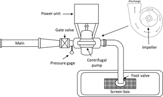
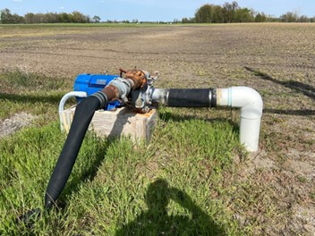
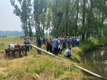
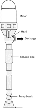
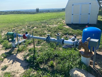
Centrifugal pumps are typically used to pump water from lakes, streams, ponds, and shallow wells. They can also be used to add pressure to a pipeline. Examples of a centrifugal pump system are shown in figures 1–3. Centrifugal pumps consist of two main parts: an impeller and a casting. The impeller (or rotor) adds energy to the water in terms of increased pressure and velocity. The casting guides the water flow to and from the impeller. Water to be pumped enters the center of the centrifugal pump and is moved rapidly outward toward the discharge orifice by the action of the impeller. The pump’s discharge can be varied by changing the speed or diameter of the impeller.
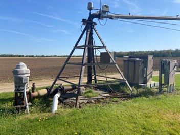
Vertical turbine pumps are generally used in deep wells but can be used with surface water systems. Examples of a vertical turbine pump are shown in figures 4 and 5. Vertical turbine pumps consist of a head assembly, shaft, column assembly, and pump bowl assembly. The efficiency of a vertical turbine pump is comparable to or greater than most centrifugal pumps. Most turbine pumps have vertical drives, and those built for service in deep wells usually have multiple impellers. These are often called multi-stage pumps, and the impeller and casing arrangements are often such that propeller flow (straight-up) and mixed flow (up at an angle) occur rather than strict centrifugal (to the side) flow.
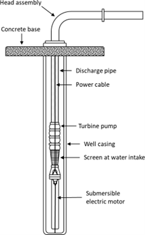
A submersible pump is generally used in deep wells and is similar to a vertical turbine pump, but it operates with a submersible electric motor (figures 6 and 7). This is more efficient than the vertical turbine design as the pump and motor are suspended in the water, eliminating the long drive shaft and bearing retainers.
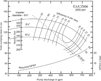
Selection of an irrigation pump can be quite confusing due to the number of models, styles, and features available. Two generally reliable sources can assist you: the manufacturers’ literature and pump dealers. The manufacturers’ literature usually describes the models available in detail concerning special features, recommended applications, and pump performance. The performance data are often presented in a graphic form as pump characteristic curves. An example of characteristic curves for a pump is shown in Figure 8. In addition, competent irrigation supply, well equipment, or pump dealers can help with pump selection. Such companies generally have had a great deal of practical experience under many different conditions with the pumps they sell and install.
Type of Power Unit
Irrigation pumps are most often driven by electric motors, internal combustion engines, or tractor power- takeoff (PTO) shafts. No one type of power unit is best for all applications. Each has its place depending upon the type of irrigation system, its location, and the management strategy of the agricultural producer.
Farmers who plan to use ponds, streams, or shallow wells for their irrigation water source should probably first consider using PTO-drive for the power source. Many agricultural enterprises own tractors of sufficient power for this purpose. The major advantage of a system such as this is the lower initial cost since the power unit is already owned. The major disadvantage is that other tasks (such as cultivation or spraying) may compete with irrigation for use of the tractor, thus creating additional management and scheduling problems. If the work schedule on a particular farm is such that a tractor is available for use as a power source during irrigation season, this can be a good choice.
Deep well turbine pumps can also use a tractor PTO for power. Such installations are a bit more complex, however, since a right-angle gear head and long drive shaft are required. A system such as this can still be quite economical if the irrigator has a spare tractor of sufficient power. Typically, a tractor is an expensive power source considering it is costly to maintain and retrofit with safety shut down equipment. It is also difficult to match the pump’s horsepower requirement needs.
Electric motors are generally the most convenient power source for irrigation pumps. Advantages include ease of control and automation, less noise, increased service life, reduced likelihood of mechanical malfunction, and increased efficiency when compared with tractor PTO and engine drives.
Electricity offers numerous benefits for irrigation as it eliminates potential environmental risks associated with storing liquid fuels near wells and surface water sources. Additionally, electric-driven pumping plants can be conveniently controlled from a distance using a remote controlling system. The higher upfront costs for purchasing pumping equipment and the increased annual maintenance expenses associated with combustion engines drive more irrigation toward adopting electric power (Kelley, 2013).
An expensive disadvantage can be the location of the water source in relation to the nearest suitable electric service.
Most farms typically have access to single-phase electric power, whereas the electric motors and control systems designed for large-scale irrigation systems are intended for three-phase power. To address this disparity, farms can use farm-supplied electric phase converters or variable frequency drive systems to generate three-phase electric power from a single- phase line. However, these solutions often come with limitations, especially for larger motors, as they aim to mitigate brownout issues on the service line. Additionally, to further mitigate brownout problems, electric service providers may mandate that farms invest in and maintain soft-start pump motors or variable frequency drive systems. These systems help reduce the startup load of the larger, high-horsepower pump motors (Kelley, 2013).
The most straightforward and secure energy source for pump locations is to have three-phase electric power supplied by your electricity service provider. Electric service providers can typically provide a cost estimate for the installation of three-phase electric power service at your specific location. In some cases, these estimates may be offered free of charge if you commit to using a certain amount of power in the future. More commonly, if three-phase power isn’t readily available near your location, the costs for installing a simple line drop from a new set of transformers on an existing three-phase line are estimated to range between $500 and $2,000. However, if three-phase power infrastructure is not nearby, the expenses for installing the service are projected to be in the range of $10,000 to $30,000 per mile, and these costs would need to be covered by the prospective irrigator to upgrade the service in that area (Kelley, 2013).
If you are using a well as the water source for irrigation, you can use electric motors of the water- tight and vertical type. These motors are of great advantage as compared to tractor PTO and engine drives in that a gear head and long drive shaft are not required. The power unit and the pump are mounted together as an integral unit and submerged in the well. One disadvantage of this type of unit is that high horsepower models require large diameter wells. Common installations are generally of 60 horsepower or less.
Internal combustion engines are probably best used for the pumping power unit when electric service is prohibitively costly, when a tractor with sufficient PTO horsepower is unavailable, or both. Engines are available that operate on a wide variety of fuels including gasoline, natural gas, diesel fuel, and propane. These engine and pump combinations are often equipped with Hi/Lo pressure switches to slow the engine down and allow a cooling period before shutting down the unit. Low oil and over-temperature safety shut down controls are also available.
Diesel engines are generally much more expensive to buy but less expensive to operate than spark ignition engines. Spark ignition engines are generally selected for relatively low power and low annual use applications. The diesel pumping plants are generally more economical for systems where 600 or more hours of annual use are anticipated and where the required horsepower is relatively high.
You should carefully consider the availability and cost of the fuels required by the various types of internal combustion engines. Unfortunately, this is becoming increasingly difficult due to the presently uncertain and changing condition of the petroleum market. Recent environmental incentives have pushed irrigators to consider natural gas, compressed natural gas, and propane as low-emission sources of power. Internal combustion engines are typically a fraction of the cost compared to diesel engines but have a shorter service life.
You should also carefully consider noise control in relation to internal combustion engine power plants. Methods other than a standard muffler are often advisable, particularly if the pumping plant is located near residences. Effective methods for reducing engine noise include installing large silencer-type mufflers (for example, electronic mufflers), placing the pumping plant in a small enclosure, and building soil embankments around pumping plant installation.
Efficiency
Efficiency, as a concept, is particularly valuable when considering the use of a scarce or expensive resource. Two such resources are used with irrigation: water and energy. Michigan irrigators are fortunate in that water is generally available. The expensive resource used by irrigation systems in Michigan is energy. It can be argued, with good reason, that water is an expensive resource in that the energy is used to transport the water. However, the farmer is paying for fuel or electricity rather than for the water itself. The water is generally free, at least for the present, but its use requires substantial financial outlay. The concept of pumping efficiency deals with the effectiveness of the irrigation pump in transferring energy from the power unit to the water it pumps. This being the case, pumping efficiency can be a major factor in the economic return realized from an irrigation system. It is a measure of how well the expensive and scarce resource, energy, is used. The efficiency of an irrigation pump is the ratio of the energy output to the energy input. The energy output of an irrigation pump is called the water horsepower (W Hp) of the pump. It can be readily calculated using equation D.
Equation D: W Hp = .00058 x flow (gpm) x total discharge head (psi)
Recalling the example situation of the corn farmer requiring a pump capable of 422 gpm at a total discharge head of 145 psi, about 35 W Hp (0.00058 x 422 x 145 = 35.49) is the required output of the pump.
Power input to an irrigation pump is the brake horsepower (B Hp) of the pumping plant. As is shown in equation E, the ratio of the water horsepower to the brake horsepower is the pumping efficiency.
Equation E: Pumping Efficiency = x 100%
A pump with higher efficiency will deliver the desired flow at the desired head with less energy consumption than a similar pump of lower efficiency. Lower energy consumption results in a lower operating cost for the pump with higher pumping efficiency.
As an illustration of the financial impact of pumping efficiency, let us assume our example irrigator happens to select an electric motor for the power unit and a centrifugal pump with 72% pumping efficiency under the anticipated operating conditions. He plans to irrigate about 960 hours per crop season, applying about 10 inches of water to the field. The electric motor is correctly sized by the local pump dealer to operate at full load with a motor efficiency of 84%. Electric power price ranges from $0.107 to $0.134 per kilowatt hour. Using these figures, the yearly pumping cost is calculated at about $5,043.
![]()
Now, let us suppose that the irrigator happens to select an irrigation pump with a 48% pumping efficiency under the anticipated conditions. We will assume that everything else is as before, with only this one difference. With this situation, the yearly pumping costs will be about $7,595.
![]()
The irrigator will spend about $1,500 more per year in pumping costs if the second pump is selected rather than the first pump. Thus, you can see that irrigation costs can be greatly influenced by pump selection.
Careful pump selection and regular repair and maintenance can serve to keep pumping efficiency at an acceptable level. One component of regular maintenance for irrigation pumping plants should be an efficiency determination. This can be readily accomplished by measuring the flow and total discharge head of the pump and calculating the water horsepower using equation D. This value is then used in equation E with the brake horsepower output of the power unit to calculate pumping efficiency. Efficiencies of 65% or more are generally acceptable for most irrigation pumps.
The performance or characteristic curves for pumps can greatly assist in the selection of an efficient pump. As shown in Figure 8, pumping efficiency performance curves allow the individual selecting the pump to compare the efficiencies of various pumps at the required flow and head.
Summary
Several types of pumps and power units are available for use with sprinkler irrigation systems. The thorough planning and careful selection of the pumping plant can reduce the cost of irrigation by reducing the energy input to the system. The first step in planning the pumping plant is to determine the required flow and head. Next, select the type of pump and power unit with consideration to the physical and managerial situations present. Pumping efficiency should be used as one of the criteria for selecting the pump. Finally, periodically check the efficiency of the irrigation pump. Seek assistance in planning and selecting pumping plants from the most competent well supply, irrigation equipment, and pump dealers. Manufacturers’ literature and performance curves are essential.
Note: Make sure your installer chooses a pump that is in the middle of the efficiency curve and installs the submersible and turbine pump intakes above the well screen not below the top of the screen.
Considerations for Planning and Selecting Pumping Plants for Sprinkler Irrigation (E3485) is based on a 1992 article of the same name by George H. Aull, Extension agricultural engineer, Department of Agricultural Engineering, Michigan State University.
References
Kelley, L. (2013). Three phase power: The first choice for irrigation energy. Michigan State University Extension. https://www.canr.msu.edu/news/three_ phase_power_the_first_choice_for_irrigation_energy